DOUBLE CONSTRAINT
Once the overall concept of a Formula 1 car has been devised and a production schedule set, the team’s engineers will now face the daunting task of drawing and producing each of the 20 000 parts that make up a modern charger!
To simplify things, the design process of the non-mechanical components (bodywork, monocoque, etc.) must take into account two key aspects: the volumes, in order to produce efficient aerodynamics, as well as rigidity to make sure the overall structure is stiff enough.
Both factors will be more or less crucial, depending on whether the part is an external or internal element. For instance, a front wing will have a certain geometry defined for aerodynamic performance but must have sufficient stiffness. Mechanical components (dampers, steering elements, transmission, brakes, etc.) must be designed for stiffness, minimum weight and function.

© Renault F1
SHAPES
Aerodynamicists have two main tools when it comes to shaping an F1 car: the wind tunnel and computational fluid dynamics (CFD).
CFD can be seen as a sort of virtual wind tunnel, which allows teams to visualise and quantify airflow structures around the car’s bodywork. Basically, they rely on CFD work to sample ideas before the most promising designs are turned into scale models that are put to the test and assessed in the actual wind tunnel.
Working in the wind tunnel does not offer the same range of opportunities as CFD in terms of visualisation since it only gives data with a set number of sensors. Still, as a non-virtual and experimental tool, the wind tunnel is the perfect complement to CFD.
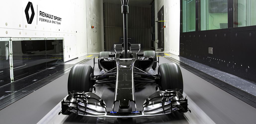
Inside their wind tunnels, F1 teams place 60% scale models in various configurations, as they seek to reproduce conditions experienced under braking (with the car pitching forwards) or through cornering (with the car rolling). The wind tunnel has a moving road to simulate the effect of the car running over the track. What aerodynamicists are looking to achieve is to generate a stable load in a wide variety of situations, instead of trying to get high downforce in a tight operating window.
Once the volumes have been set, detailed drawing of the car comes next with the help of computer-aided design (CAD) software. The team thus embarks on an ongoing iterative process as it goes back and forth between aerodynamics, finite element analysis for strength and stiffness and detailed design. Indeed, while designing an F1 component is based on aero principles, stiffness and weight must be taken into account as well.

 '
'

