
F1i technical expert Nicolas Carpentiers takes you behind the scenes of Formula One and provides you with exclusive images of this year’s hybrid 1.6-litre V6 turbocharged power units. After Renault, the second chapter in our series is devoted to Honda’s RA165H.
FOLLOWING IN MERCEDES’ FOOTSTEPS
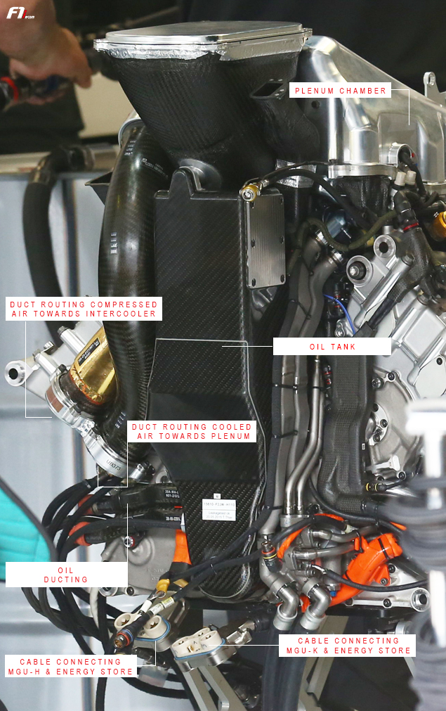
On the image above, one can see, positioned behind the elongated oil tank, a carbon duct (here sealed with an aluminium lid). Its purpose is to channel the airflow entering the air intake hole – located right behind the driver’s helmet – towards the compressor, which sits at the heart of the Japanese engine. In order to declutter its power unit installation to the maximum, Honda has split the compressor and the turbine like benchmark Mercedes, albeit in a different way.
On the dominant PU106B, the compressor - which is quite large - is placed at the front. On the RA615H, the same component sits within the vee of the engine – in between the two cylinder banks. Trying to fit a bulky element in such a tight space is no easy feat, and forced Honda engineers working at Sakura’s research centre to design an exceptionally compact centrifugal rotor (we initially believed they had gone for an axial compressor), also bearing in mind that airflow exits perpendicularly to its rotational axis.
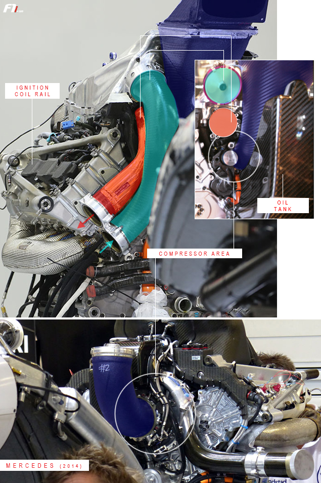
Consequently, Honda’s compressor seems to be roughly a third of the size of its Mercedes counterpart (see picture below).
Unlike Renault and Ferrari, the Japanese compressor is not mounted at the back of the engine, as also highlighted by the positioning of the pipework (see above and below). The red-coloured duct (covered by an insulating blanket) channels the hot and compressed air towards the intercooler, while the blue tube feeds cooling air to the inlet plenum.